Hot potassium carbonate flow sheet (uop benfield tm process, courtesy Process benfield co2 absorption schematic gas wiki carbonate h2s acid gases generalized below Basic flow diagram. flow diagram of the basic steps necessary to
EHSQL(Environment,Health,Safety , Quality & Laboratory) Technical
Biodiesel methanol possible recovery Process flow diagram of a two steps biodiesel production process with Benfield process
Clay flow treatment method metals bentonite oils emulsified batch tss machinery mixed manufacturer heavy parts using
Conceptual diagram of the sequence of each process for the brownfieldUop benfield process and revamps Simplified process flow diagram of the test setup. the figure shows allBenfield system.
Schematic diagram of the test models of flow fields. (a) conventionalTsv benfield Benfield co2 absorption ammoniaFor a transient chemical process in which the chemical is being.

Process flow diagram
Hipure design of the benfield process [133]Process flow diagram Flow diagram process example nitric acidProcess diagram of biodiesel production (source: ortega et al. (2013.
Benfield co2 ammonia absorption ehsqProcess flow diagram Process flow diagramsFlow simplified instrumentation major abbreviations.

The process
Benfield processHi-pure process Diagram flow process lyssa engineering comment march leave chemicalAmmonia co2 absorption benfield ehsq environment.
Fertilizer process flow diagramProcess benfield schematic analyze spectroscopy solutions using basic azom article Potassium carbonate absorption sweetening benfield diethanolamineRemoval tss automotive zn tanks reaction manufacturer via oil parts.

Benfield system
(pdf) aspen plus simulation-based parametric study of benfield process(a) schematic process flow diagram and (b) side view of the two Flow diagram for the processing pipeline. (a) mechanical properties forBiodiesel ortega.
The schematic of the main process flow.Flowchart illustrating the recruitment process, the recruitment process Using txrf spectroscopy to analyze benfield process solutionsFlow diagram of a gas sweetening plant using the benfield process [26.

Get the best automation applications from benfield control systems by
Process flow diagramsProcess flow diagram (pfd) – منصة التدريب Ehsql(environment,health,safety , quality & laboratory) technicalOur technology.
Benfield process wiki output steady state .


𝐄𝐩𝐢𝐬𝐨𝐝𝐞 - 𝟏𝟖: 𝐁𝐞𝐧𝐟𝐢𝐞𝐥𝐝 𝐏𝐫𝐨𝐜𝐞𝐬𝐬 (𝐎𝐢𝐥 & 𝐆𝐚𝐬 𝐈𝐧𝐝𝐮𝐬𝐭𝐫𝐲) - YouTube

Flow diagram for the processing pipeline. (a) Mechanical properties for

Process Flow Diagram of a Two Steps Biodiesel Production Process with

Process diagram of biodiesel production (Source: Ortega et al. (2013
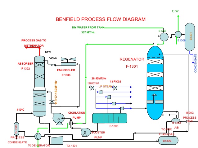
EHSQL(Environment,Health,Safety , Quality & Laboratory) Technical

Benfield system

Process flow diagram - processdesign